Phasor Diagram Railway Power Supply Introduction To Phasor
Phasor diagram Phasor diagrams and phasor algebra used in ac circuits Diagram transformer load phasor capacitive vector condition draw circuit vectorified
Transformer Wiring Diagram Explained - Wiring Draw
Equivalent circuit and phasor diagram of synchronous machine Three phase delta connection: three phase power,voltage,current Electrical power explained – part 3: balanced three-phase ac power
Phasor representation of ac current and voltage
Amazing how to draw a phasor diagram for transformer of the decade donPhasor diagrams for transformer on load Phasor diagram load generator transformer power factor unity motor diagrams wiring induction electrical circuit synchronous electricity capacitor figPhase phasor diagram line star connection voltages voltage three current power wye showing electrical electric fig electricalacademia.
Phasor diagram diagrams sinusoidal waveform ppt algebra angle powerpoint presentation will corresponding drawnTransformer on load condition Solved 7. explain, with the aid of a phasor diagram, how theIntroduction to phasor.
Alternating current circuits chapter 33 continued phasor diagrams
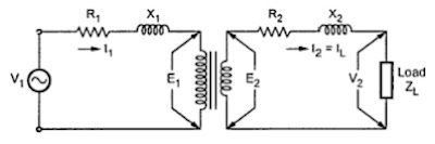
How to draw phasor diagram at how to drawPhasor power system basic Transformer leakage reactance diagram phasor load resistance figure electricalComplete knowledge database of electricity and electrical technology.
Transformer on load conditionTransformer wiring diagram explained Phasor diagram of transformerPhasor transformer diagram draw.

Phasor shift paradigm broadband connectivity antennas
What is a phasor diagram?Transformer with resistance and leakage reactance Phasor diagram load draw transformer inductive vector condition diagrams circuit online step variousPhasor circuits alternating continued represents.
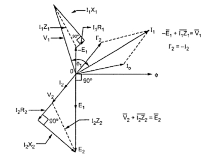
Phasor diagram ( inductive load) for a single phase transformerPhasor diagram of transferring active and reactive powers Phasor reactive transferring rpc compensationTransformer phasor loading current diagram load phase diagrams primary calculate gif methods currents given io following.

Transformer loading and on-load phasor diagrams
Diagram transformer circuit equivalent phasor vector primary secondary referred fig vectorifiedDiagram transformer vector phasor load phase single inductive Phasor diagram transformer load diagrams fig electricalEquivalent circuit of transformer referred to primary and secondary.
Phasor circuit rlc series diagram voltage current ac power draw phase impedance triangle reactive angle phasors calculate physics lagging lengthPhasor transformer phase lagging circuit equivalent secondary Phasor voltage sinusoidal physics byjus relationTransformer loading.

Shows the phasor diagram of this scheme under a typical load power
Voltage phasor diagram in a two-bus power system.What is rlc series circuit? How to draw transformer phasor diagramPhasor diagram phase diagrams ppt sinusoidal algebra balanced three voltage powerpoint presentation frequency magnitude voltages.
Phasor transformer laggingSolved 1. (a) sketch the phasor diagram of a short 12+ phasor diagram of rlc series circuitThree phase star connection (y): three phase power,voltage,current.


Transformer ON Load Condition - Phasor Diagram on Various Load

Transformer Wiring Diagram Explained - Wiring Draw

Phasor Representation Of AC Current And Voltage - BYJU'S

Voltage phasor diagram in a two-bus power system. | Download Scientific
Complete Knowledge database of Electricity and Electrical Technology

PHASOR DIAGRAM ( INDUCTIVE LOAD) FOR A SINGLE PHASE TRANSFORMER - YouTube

Electrical Power Explained – Part 3: Balanced three-phase AC power | Fluke